Facebook
 Google
 GitHub
 Linkedin
AC Electric Circuits
Series and Parallel AC Circuits
75 questions By Tony R. Kuphaldt
-
Question 58 of 75
Solve for all voltages and currents in this series RC circuit:

Reveal answerVC = 14.39 volts RMS
VR = 4.248 volts RMS
I = 903.9 μA RMS
Follow-up question: identify the consequences of a shorted capacitor in this circuit, with regard to circuit current and component voltage drops.
Notes:Nothing special here - just a straightforward exercise in series AC circuit calculations.
Students often have difficulty formulating a method of solution: determining what steps to take to get from the given conditions to a final answer. While it is helpful at first for you (the instructor) to show them, it is bad for you to show them too often, lest they stop thinking for themselves and merely follow your lead. A teaching technique I have found very helpful is to have students come up to the board (alone or in teams) in front of class to write their problem-solving strategies for all the others to see. They don’t have to actually do the math, but rather outline the steps they would take, in the order they would take them. The following is a sample of a written problem-solving strategy for analyzing a series resistive-reactive AC circuit:
Step 1: Calculate all reactances (X).
Step 2: Draw an impedance triangle (Z ; R ; X), solving for Z
Step 3: Calculate circuit current using Ohm’s Law: I = V/Z
Step 4: Calculate series voltage drops using Ohm’s Law: V = I Z
Step 5: Check work by drawing a voltage triangle (Vtotal ; V1 ; V2), solving for Vtotal
By having students outline their problem-solving strategies, everyone gets an opportunity to see multiple methods of solution, and you (the instructor) get to see how (and if!) your students are thinking. An especially good point to emphasize in these “open thinking” activities is how to check your work to see if any mistakes were made.
-
Question 59 of 75
A technician needs to know the value of a capacitor, but does not have a capacitance meter nearby. In lieu of this, the technician sets up the following circuit to measure capacitance:
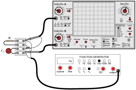
You happen to walk by this technician’s workbench and ask, “How does this measurement setup work?” The technician responds, “You connect a resistor of known value (R) in series with the capacitor of unknown value (Cx), then adjust the generator frequency until the oscilloscope shows the two voltage drops to be equal, and then you calculate Cx.”
Explain how this system works, in your own words. Also, write the formula you would use to calculate the value of Cx given f and R.
Reveal answerI’ll let you figure out how to explain the operation of this test setup. The formula you would use looks like this:
Cx = 1 2 πf RFollow-up question: could you use a similar setup to measure the inductance of an unknown inductor Lx? Why or why not?
Challenge question: astute observers will note that this setup might not work in real life because the ground connection of the oscilloscope is not common with one of the function generator’s leads. Explain why this might be a problem, and suggest a practical solution for it.
Notes:This method of measuring capacitance (or inductance for that matter) is fairly old, and works well if the unknown component has a high Q value.
-
Question 60 of 75
If the dielectric substance between a capacitor’s plates is not a perfect insulator, there will be a path for direct current (DC) from one plate to the other. This is typically called leakage resistance, and it is modeled as a shunt resistance to an ideal capacitance:

Calculate the magnitude and phase shift of the current drawn by this real capacitor, if powered by a sinusoidal voltage source of 30 volts RMS at 400 Hz:

Compare this against the magnitude and phase shift of the current for an ideal capacitor (no leakage).
Reveal answerI = 56.548671 mA ∠ 89.98o for the real capacitor with leakage resistance.
I = 56.548668 mA ∠ 90.00o for the ideal capacitor.
Notes:Discuss with your students the fact that electrolytic capacitors typically have more leakage (less Rleakage) than most other capacitor types, due to the thinness of the dielectric oxide layer.
Students often have difficulty formulating a method of solution: determining what steps to take to get from the given conditions to a final answer. While it is helpful at first for you (the instructor) to show them, it is bad for you to show them too often, lest they stop thinking for themselves and merely follow your lead. A teaching technique I have found very helpful is to have students come up to the board (alone or in teams) in front of class to write their problem-solving strategies for all the others to see. They don’t have to actually do the math, but rather outline the steps they would take, in the order they would take them. The following is a sample of a written problem-solving strategy for analyzing a series resistive-reactive AC circuit:
Step 1: Calculate all reactances (X).
Step 2: Draw an impedance triangle (Z ; R ; X), solving for Z
Step 3: Calculate circuit current using Ohm’s Law: I = V/Z
Step 4: Calculate series voltage drops using Ohm’s Law: V = I Z
Step 5: Check work by drawing a voltage triangle (Vtotal ; V1 ; V2), solving for Vtotal
By having students outline their problem-solving strategies, everyone gets an opportunity to see multiple methods of solution, and you (the instructor) get to see how (and if!) your students are thinking. An especially good point to emphasize in these “open thinking” activities is how to check your work to see if any mistakes were made.