Facebook
 Google
 GitHub
 Linkedin
AC Electric Circuits
Series and Parallel AC Circuits
75 questions By Tony R. Kuphaldt
-
Question 67 of 75
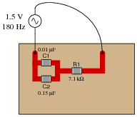
Calculate the voltage drops across all components in this circuit, expressing them in complex (polar) form with magnitudes and phase angles each:
Reveal answerVC1 = 0.921 V ∠−52.11o
VC2 = 0.921 V ∠−52.11o
VR1 = 1.184 V ∠ 37.90o
Follow-up question: how much phase shift is there between the capacitors’ voltage drop and the resistor’s voltage drop? Explain why this value is what it is.
Notes:The first challenge of this question is for students to figure out how to reduce this series-parallel combination to something simpler. Fortunately, this is very easy to do if one remembers the properties of parallel capacitances.
Students may be surprised to discover the phase shift between VC and VR is the value it is. However, this should not remain a mystery. Discuss this with your class, taking time for all of them to understand why the voltage phasors of a resistor and a capacitor in a simple series circuit will always be orthogonal.
Students often have difficulty formulating a method of solution: determining what steps to take to get from the given conditions to a final answer. While it is helpful at first for you (the instructor) to show them, it is bad for you to show them too often, lest they stop thinking for themselves and merely follow your lead. A teaching technique I have found very helpful is to have students come up to the board (alone or in teams) in front of class to write their problem-solving strategies for all the others to see. They don’t have to actually do the math, but rather outline the steps they would take, in the order they would take them. The following is a sample of a written problem-solving strategy for analyzing a series resistive-reactive AC circuit:
Step 1: Calculate all reactances (X).
Step 2: Draw an impedance triangle (Z ; R ; X), solving for Z
Step 3: Calculate circuit current using Ohm’s Law: I = V/Z
Step 4: Calculate series voltage drops using Ohm’s Law: V = I Z
Step 5: Check work by drawing a voltage triangle (Vtotal ; V1 ; V2), solving for Vtotal
By having students outline their problem-solving strategies, everyone gets an opportunity to see multiple methods of solution, and you (the instructor) get to see how (and if!) your students are thinking. An especially good point to emphasize in these “open thinking” activities is how to check your work to see if any mistakes were made.
-
Question 68 of 75
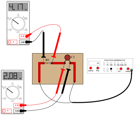
Determine the phase angle (Θ) of the current in this circuit, with respect to the supply voltage:
Reveal answerΘ = 26.51o
Challenge question: explain how the following phasor diagram was determined for this problem:

Notes:This is an interesting question for a couple of reasons. First, students must determine how they will measure phase shift with just the two voltage indications shown by the meters. This may present a significant challenge for some. Discuss problem-solving strategies in class so that students understand how and why it is possible to determine Θ.
Secondly, this is an interesting question because it shows how something as abstract as phase angle can be measured with just a voltmeter - no oscilloscope required! Not only that, but we don’t even have to know the component values either! Note that this technique works only for simple circuits.
A practical point to mention here is that multimeters have frequency limits which must be considered when taking measurements on electronic circuits. Some high-quality handheld digital meters have frequency limits of hundred of kilohertz, while others fail to register accurately at only a few thousand hertz. Unless we knew these two digital voltmeters were sufficient for measuring at the signal frequency, their indications would be useless to us.
-
Question 69 of 75
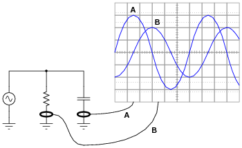
Calculate the total (source) current in this parallel RC circuit, based on the readings taken by the dual-trace oscilloscope (both of the inductive current probes show branch currents in units of 1 amp per division):
Itotal =
Reveal answerItotal = 3.61 amps peak or 2.55 amps RMS
Notes:This is a really simple trigonometry problem, disguised by the necessity of having to interpret the oscilloscope display.