Facebook
 Google
 GitHub
 Linkedin
AC Electric Circuits
Series and Parallel AC Circuits
75 questions By Tony R. Kuphaldt
-
Question 73 of 75
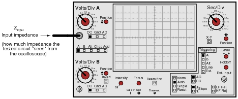
The input impedance of an electrical test instrument is a very important parameter in some applications, because of how the instrument may load the circuit being tested. Oscilloscopes are no different from voltmeters in this regard:
Typical input impedance for an oscilloscope is 1 MΩ of resistance, in parallel with a small amount of capacitance. At low frequencies, the reactance of this capacitance is so high that it may be safely ignored. At high frequencies, though, it may become a substantial load to the circuit under test:
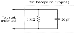
Calculate how many ohms of impedance this oscilloscope input (equivalent circuit shown in the above schematic) will impose on a circuit with a signal frequency of 150 kHz.
Reveal answerZinput = 52.98 kΩ at 150 kHz
Follow-up question: what are the respective input impedances for ideal voltmeters and ideal ammeters? Explain why each ideal instrument needs to exhibit these impedances in order to accurately measure voltage and current (respectively) with the least “impact” to the circuit under test.
Notes:Mention to your students that this capacitive loading effect only gets worse when a cable is attached to the oscilloscope input. The calculation performed for this question is only for the input of the oscilloscope itself, not including whatever capacitance may be included in the test probe cable!
This is one of the reasons why ×10 probes are used with oscilloscopes: to minimize the loading effect on the tested circuit.
-
Question 74 of 75
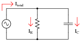
If the source voltage in this circuit is assumed to be the phase reference (that is, the voltage is defined to be at an angle of 0 degrees), determine the relative phase angles of each current in this parallel circuit:
- ΘI(R) =
- ΘI(C) =
- ΘI(total) =
Reveal answer- ΘI(R) = 0o
- ΘI(C) = 90o
- ΘI(total) = some positive angle between 0o and 90o, exclusive
Notes:Some students will be confused about the positive phase angles, since this is a capacitive circuit and they have learned to associate negative angles with capacitors. It is important for these students to realize, though, that the negative angles they immediately associate with capacitors are in reference to impedance and not necessarily to other variables in the circuit!
-
Question 75 of 75
Calculate the voltage dropped across the inductor, the capacitor, and the 8-ohm speaker in this sound system at the following frequencies, given a constant source voltage of 15 volts:

- f = 200 Hz
- f = 550 Hz
- f = 900 Hz
Regard the speaker as nothing more than an 8-ohm resistor.
Reveal answer- f = 200 Hz ; VL = 1.750 V ; VC = 11.79 V ; Vspeaker = 5.572 V
- f = 550 Hz ; VL = 6.472 V ; VC = 5.766 V ; Vspeaker = 7.492 V
- f = 900 Hz ; VL = 9.590 V ; VC = 3.763 V ; Vspeaker = 6.783 V
This circuit is known as a midrange crossover in stereo system design.
Notes:This is an interesting circuit to analyze. Note how, out of the three frequency points we performed calculations at, the speaker’s voltage is greatest at the middle frequency. Note also how the inductor and capacitor drop very disparate amounts of voltage at the high and low frequencies. Discuss this circuit’s behavior with your students, and ask them what practical function this circuit performs.
Students often have difficulty formulating a method of solution: determining what steps to take to get from the given conditions to a final answer. While it is helpful at first for you (the instructor) to show them, it is bad for you to show them too often, lest they stop thinking for themselves and merely follow your lead. A teaching technique I have found very helpful is to have students come up to the board (alone or in teams) in front of class to write their problem-solving strategies for all the others to see. They don’t have to actually do the math, but rather outline the steps they would take, in the order they would take them. The following is a sample of a written problem-solving strategy for analyzing a series resistive-reactive AC circuit:
Step 1: Calculate all reactances (X).
Step 2: Draw an impedance triangle (Z ; R ; X), solving for Z
Step 3: Calculate circuit current using Ohm’s Law: I = V/Z
Step 4: Calculate series voltage drops using Ohm’s Law: V = I Z
Step 5: Check work by drawing a voltage triangle (Vtotal ; V1 ; V2), solving for Vtotal
By having students outline their problem-solving strategies, everyone gets an opportunity to see multiple methods of solution, and you (the instructor) get to see how (and if!) your students are thinking. An especially good point to emphasize in these “open thinking” activities is how to check your work to see if any mistakes were made.