This FEQ (Frequent Engineering Question) gives you essential information about the most important and widespread technique for converting a theoretical circuit…
This FEQ (Frequent Engineering Question) gives you essential information about the most important and widespread technique for converting a theoretical circuit into a functional physical device.

This FEQ (or Frequent Engineering Question) covers the basics of a crucial topic: hardware description languages.
This FEQ (or Frequent Engineering Question) covers the basics of a crucial topic: hardware description languages.

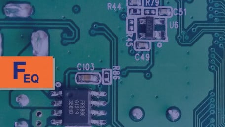
In this FEQ (Frequent Engineering Question), we'll take a look at the advantages of zero-ohm resistors and where they're…
In this FEQ (Frequent Engineering Question), we'll take a look at the advantages of zero-ohm resistors and where they're most suitable in design.

Learn how simulating a voltage buffer can help you implement it more effectively to boost the output current drive of an op-amp.
Learn how simulating a voltage buffer can help you implement it more effectively to boost the output current drive of an op-amp.

In this entry of our Frequent Engineering Questions (FEQ) series, learn the basics of how a load line can be used in…
In this entry of our Frequent Engineering Questions (FEQ) series, learn the basics of how a load line can be used in designing circuits.

In this article, we’ll perform some classification experiments and gather data on the relationship between hidden-layer…
In this article, we’ll perform some classification experiments and gather data on the relationship between hidden-layer dimensionality and network performance.

Learn a method of attaining convergence when simulating very high Q crystal oscillators using Cadence’s Virtuoso…
Learn a method of attaining convergence when simulating very high Q crystal oscillators using Cadence’s Virtuoso Periodic Steady State (PSS) analysis.

This article looks at the common options for a four-layer board stackup.
This article looks at the common options for a four-layer board stackup.

This article discusses the major causes of high temperatures on PCBs that cause failure and damage to the board itself.
This article discusses the major causes of high temperatures on PCBs that cause failure and damage to the board itself.

This article will discuss how to implement a shift register in Verilog. The register described can be synthesized and…
This article will discuss how to implement a shift register in Verilog. The register described can be synthesized and downloaded to an FPGA for test in actual hardware.

Learn about heterogeneous and homogenous buses, special IC packages, and more!
Learn about heterogeneous and homogenous buses, special IC packages, and more!

This article presents tools and practices in reducing errors in your schematics.
This article presents tools and practices in reducing errors in your schematics.

Learn how to use the gridded ground technique to reduce noise in a double-sided PCB.
Learn how to use the gridded ground technique to reduce noise in a double-sided PCB.

The design of a modern IC is a truly monumental undertaking, and IC design tools make the job possible.
The design of a modern IC is a truly monumental undertaking, and IC design tools make the job possible.

Learn best layout practices for your DC-DC buck converter circuits.
Learn best layout practices for your DC-DC buck converter circuits.

Learn how to measure noise using LTspice for op-amp circuits with handy examples.
Learn how to measure noise using LTspice for op-amp circuits with handy examples.

Learn how to interface with LTSpice using WAV files.
Learn how to interface with LTSpice using WAV files.

Learn multiple ways to simulate noise sources—for both transient and noise analysis—in LTspice.
Learn multiple ways to simulate noise sources—for both transient and noise analysis—in LTspice.

Where can EEs use Python in their day to day? Here's a look at the applications where Python excels.
Where can EEs use Python in their day to day? Here's a look at the applications where Python excels.

Learn about simulating an interesting current source built around an op-amp and an instrumentation amplifier.
Learn about simulating an interesting current source built around an op-amp and an instrumentation amplifier.
 Facebook
 Google
 GitHub
 Linkedin